Selecting a hydronic pump requires more than entering a building height and choosing a circulator. In a closed-loop chilled-water or heating-water system, the pump must overcome the friction and component losses along the critical circuit while maintaining the required design flow.
This article explains a practical method for calculating preliminary closed-loop hydronic pump head and highlights several common design mistakes.
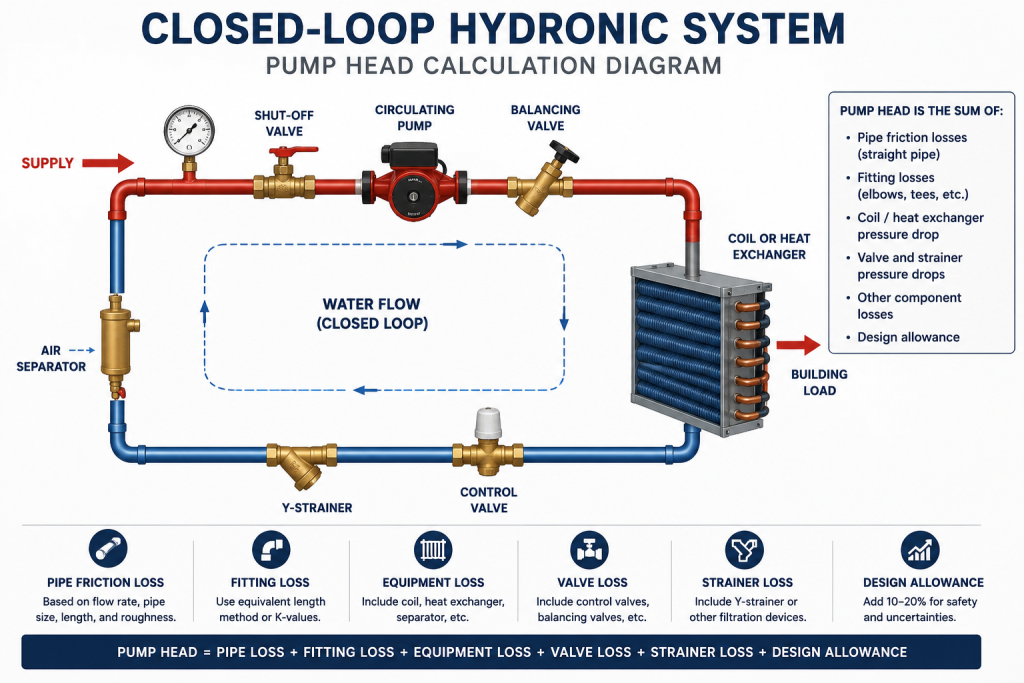
What Is Pump Head?
Pump head represents the mechanical energy added to the circulating fluid by the pump. In HVAC design, it is commonly expressed in feet of head.
As water flows through piping, fittings, coils, valves, strainers, and heat exchangers, pressure is lost due to friction. The pump must provide enough head to overcome these losses and maintain the required flow rate.
Do You Add the Building Height?
For a typical closed-loop hydronic system, building height is not added directly to the circulating pump head.
The water rising through the supply pipe is balanced by water returning through the return pipe. The circulating pump is therefore selected primarily to overcome friction and component losses in the operating circuit.
Static fill pressure, expansion-tank sizing, air separation, and minimum system pressure must still be reviewed separately. These items are important, but they are not the same as circulating pump head.
Step 1: Calculate the Required Flow Rate
For water systems, the common HVAC relationship is:
GPM = Load ÷ (500 × ΔT)
where:
- GPM = required water flow rate
- Load = heating or cooling load, Btu/hr
- 500 = approximate water heat-transfer factor
- ΔT = entering-to-leaving water temperature difference, °F
For glycol systems, use a corrected fluid factor based on the fluid density and specific heat.
Flow Example
A chilled-water coil has a cooling load of 240,000 Btu/hr and a water-side temperature difference of 20°F.
GPM = 240,000 ÷ (500 × 20)
GPM = 24
The preliminary design flow is therefore 24 GPM.
Step 2: Identify the Critical Circuit
In a system with multiple branches, the pump does not need to overcome the sum of every branch pressure drop.
Instead, identify the critical circuit: the path from the pump through the supply piping, the most hydraulically demanding terminal unit or branch, and the return piping back to the pump.
The critical circuit is usually the path with the highest combined head loss at design flow.
Step 3: Calculate Straight-Pipe Pressure Drop
Straight-pipe pressure drop depends on:
- Flow rate
- Pipe size and internal diameter
- Pipe length
- Pipe roughness
- Fluid properties
- Water temperature
The Darcy-Weisbach relationship is commonly used for more detailed calculations:
hf = f × (L ÷ D) × (V² ÷ 2g)
where:
- hf = friction head loss, ft
- f = Darcy friction factor
- L = pipe length, ft
- D = internal diameter, ft
- V = water velocity, ft/s
- g = gravitational acceleration, approximately 32.2 ft/s²
Step 4: Add Fitting Equivalent Length
Elbows, tees, valves, reducers, and other fittings add resistance to the system.
A practical preliminary method is to convert each fitting into an equivalent pipe length, then add that value to the straight-pipe length.
Total Equivalent Length = Straight Pipe Length + Fitting Equivalent Length
For final design, use project-specific fitting data or manufacturer pressure-drop values where available.
Step 5: Add Equipment and Valve Pressure Drops
The critical circuit may also include:
- Cooling or heating coil
- Control valve
- Balancing valve
- Strainer
- Air separator
- Heat exchanger
- Boiler or chiller evaporator
- Other hydronic equipment
Use manufacturer data whenever possible. Equipment pressure drops should be added to the piping head loss along the critical path.
Step 6: Calculate Total Pump Head
A practical preliminary relationship is:
Total Pump Head = Pipe Head Loss + Fitting Loss + Coil Loss + Valve Loss + Equipment Loss + Design Allowance
Pump-Head Example
Assume the critical circuit includes:
- Supply and return piping: 12 ft
- Cooling coil: 10 ft
- Control valve: 8 ft
- Strainer: 3 ft
- Additional allowance: 5 ft
Total Pump Head = 12 + 10 + 8 + 3 + 5
Total Pump Head = 38 ft
A preliminary pump selection should therefore be reviewed near:
24 GPM at approximately 38 ft of head
The final pump should be checked against the manufacturer pump curve, system curve, operating range, efficiency, and project requirements.
Common Design Mistakes
- Adding the full building height to circulating pump head in a closed-loop system
- Ignoring control-valve pressure drop
- Ignoring strainer and equipment losses
- Using the sum of all branch losses instead of the critical circuit
- Selecting pipe sizes without checking velocity and pressure drop
- Using the standard water factor for glycol systems without correction
- Adding excessive safety factor and oversizing the pump
Download the HVACICI Hydronic Calculator
Use the free HVACICI workbook to estimate hydronic coil flow, pipe sizing, pipe pressure drop, fitting equivalent length, and preliminary pump head for chilled-water and heating-water systems.
Open Hydronic Flow & Pump Head Calculator
Need Project-Specific Engineering Support?
Submit your project information for hydronic-system review, pipe-sizing assessment, pump-head calculation, or broader HVAC design support.
Request Project-Specific Review