Cooling and Dehumidification on a Psychrometric Chart
This practical training page explains how to understand cooling and dehumidification process lines on a psychrometric chart for HVAC design.
This topic is especially useful for cooling coil analysis, supply air condition, latent load control, humidity ratio reduction, apparatus dew point, bypass factor, and room sensible heat ratio review.
What Cooling and Dehumidification Means
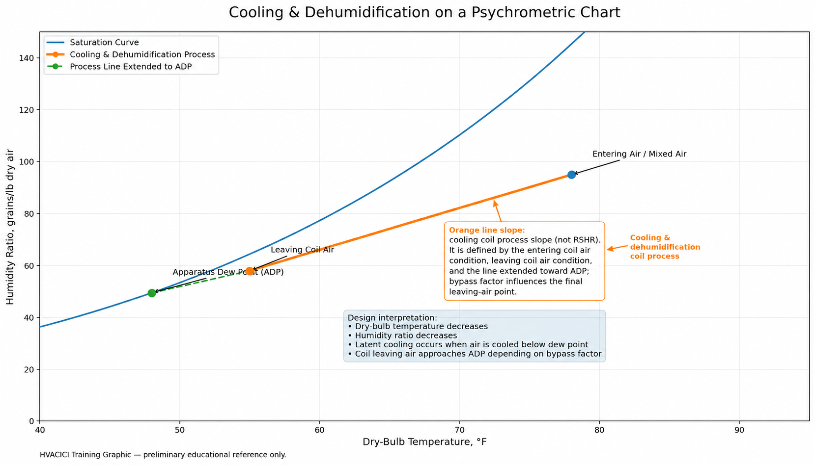
Cooling and dehumidification process showing entering coil air, leaving coil air, apparatus dew point, and the coil process slope. The orange line is a cooling coil process line, not an RSHR line.
Cooling and dehumidification occurs when air is cooled below its dew point so that moisture is removed from the air. On a psychrometric chart, this process generally moves down and to the left, showing both a reduction in dry-bulb temperature and a reduction in humidity ratio.
Why This Process Matters in HVAC Design
- It helps determine the cooling coil leaving air condition.
- It connects sensible and latent cooling performance.
- It helps evaluate whether the supply air condition can satisfy the room load.
- It shows whether moisture removal is occurring.
- It supports coil selection, ventilation review, and humidity control decisions.
Key Points on the Psychrometric Chart
- Entering Air Condition: mixed air or return air entering the cooling coil.
- Leaving Air Condition: air condition after the cooling coil.
- Apparatus Dew Point: the effective coil surface condition that the process line approaches.
- Bypass Factor: the portion of air that effectively bypasses full contact with the coil surface.
- Room Sensible Heat Ratio: the relationship between room sensible load and room total load.
Basic Cooling Formulas
Sensible Cooling:
Qsensible = 1.08 × CFM × ΔT
Latent Cooling:
Qlatent = 0.68 × CFM × Δgrains
Total Cooling:
Qtotal = 4.5 × CFM × Δh
Room Sensible Heat Ratio:
RSHR = Room Sensible Heat / Room Total Heat
Practical Design Process
- Identify the entering air condition to the cooling coil.
- Determine the required supply air temperature based on room sensible load and airflow.
- Check whether the supply air humidity ratio is realistic compared with saturation at the selected supply air temperature.
- Review the room sensible heat ratio and process line direction.
- Estimate whether dehumidification is required or whether sensible cooling only is sufficient.
- Review apparatus dew point and bypass factor if coil performance needs closer evaluation.
Common Engineering Mistakes
- Assuming a supply air temperature without checking humidity ratio.
- Ignoring latent load when outdoor air quantity is high.
- Using room sensible heat ratio without understanding the actual coil leaving air condition.
- Assuming ERV/HRV benefit without checking the actual outdoor air condition entering the coil.
- Confusing room process line with coil process line.
Video Status
Video Explanation
This video explains cooling and dehumidification on a psychrometric chart, including the cooling coil process line, apparatus dew point, and humidity ratio reduction.